Correcting Fit Issues in Dental Zirconia Implant Crowns: A Lab Problem Guide
Zirconia implant crowns miss fit for five repeatable reasons: a marginal gap at the crown-to-abutment interface, interproximal contact error, occlusal interference, screw channel misalignment, and chipping or cracking at the margin after sintering. Each one originates at a different point in the digital chain, and each one takes a different correction. Adjusting the finished crown treats the symptom, not the cause.
This guide is written for dental labs that mill implant superstructures from a dental zirconia block. It separates the failure modes, standardizes the milling and sintering steps that decide green-state and sintered geometry, and shows where digital scanbody workflows are used to verify contacts before the restoration is finished, which is still the stage where correction is cheap.
Why Fit Behaves Differently on an Implant Superstructure
A tooth-supported crown seats on a prepared tooth and can absorb small deviations inside the cement film. An implant crown seats on a dental implant abutment, and its fit depends on a chain of interfaces: the implant platform to the abutment, the abutment to the scanbody or implant library used in CAD, the designed geometry to the milled geometry, and the milled geometry to the sintered geometry.
Two consequences follow. First, an error created anywhere in that chain shows up at the margin, which is why the symptom rarely identifies the cause. Second, a zirconia crown is milled in a pre-sintered green state and then densified in a dental sintering furnace, so deviations present before sintering are carried into the final restoration rather than absorbed.
That leaves three stages a laboratory can actually control: the data set, the milling process and the sintering process. Every step in the protocol below maps back to one of them.
Problem Definition: Five Fit Failure Modes and What Actually Causes Them
1. Marginal gap at the crown-to-abutment interface
A marginal gap appears as a visible discrepancy at the interface, a crown that rocks when seated on the abutment, or an open margin on the working model. The usual mechanical causes are a scanbody that was not fully seated when it was scanned, worn or mismatched dental milling burs that leave the intaglio margin under-milled, and incorrect shrinkage compensation for the block being used. Residue left in the intaglio surface, and over-polishing of the fit surface during finishing, produce the same symptom on an otherwise accurate crown.
The fastest way to separate the causes is to dry-seat the milled green crown on the abutment analog before sintering. If the green crown seats and the sintered crown does not, the answer is in the sintering program or the blank. If it does not seat in either state, the error is upstream, in the data set or in milling.
2. Interproximal contact error
Contact that is too tight prevents the crown from seating fully; contact that is too open leaves a food trap. Both are contact errors, and both are usually designed or measured rather than machined into the crown. Sources include scanner data quality, scanbody position, the contact strength set in CAD, the shrinkage behaviour of the block, and distortion of the restoration during sintering.
Verification belongs in two places: in the design software before milling, and on the physical model after sintering. Comparing the digital model recorded before sintering with the one recorded after sintering shows whether the deviation came from the design or from the furnace cycle.
3. Occlusal interference and high spots
An implant crown cannot be corrected the way a tooth-supported crown can. There is no periodontal ligament to let the natural tooth intrude, so an occlusal high spot stays a high spot. The cause is normally an unverified opposing scan, an occlusion set in CAD without a reliable antagonist reference, or distortion across a long-span restoration during sintering. The correction has to happen in the design, not in the patient's mouth.
4. Screw channel misalignment
When a screw will not pass cleanly through the channel, the cause is generated in CAD and CAM rather than in the furnace. The screw channel is defined by the implant library and reproduced by the milling machine, so a binding or offset channel points to a library mismatch, a scanbody indexing error, or a CAM file that does not reproduce the channel as designed.
5. Chipping and cracks at the margin after sintering
This is the failure mode with a clearly documented cause chain. The trigger is an improper sintering profile setting combined with inherent defects inside the zirconia blank. The published mitigation is straightforward: follow the recommended sintering profile, and inspect blanks before sintering. A blank that has chipped or cracked should be scrapped and must not be used for a final restoration.
Industry Background: Where Zirconia Sits in Digital Implant Prosthetics
The scale of the zirconia category explains why lab protocols are under pressure to be standardized. The global zirconia-based dental materials market was valued at USD 1.2 billion in 2025 and is projected to reach USD 2.3 billion by 2033, according to Grand View Research. Within that category, zirconia discs held the largest revenue share at 63.1% in 2025, and dental labs remain the dominant end user with a 45.3% share in the same year.
The process split matters more for fit than the market size. CAD/CAM milling accounted for 82.4% of zirconia dental manufacturing process revenue in 2025, also reported by Grand View Research, which places most of the category's value and most of its geometric risk in the milling step. The 3Y-TZP grade alone held a 35.9% revenue share of the dental zirconia market in 2025, and the United States accounts for 40% of revenue in the global zirconia-based dental materials market.
Regulation adds a second layer. Under EU MDR 2017/745, most dental implants and restorative materials are classified as high-risk devices requiring intensive clinical data, according to the European Commission. For a lab working on implant superstructures, fit and material documentation are therefore not only technical issues but part of the file that supports the restoration.
Detailed Solution: Standardizing the Three Controllable Stages
Stage 1 - Data acquisition with scanbody workflows
Every geometric decision downstream inherits the scan. For implant cases, that means the scanbody. A scanbody that is not fully seated, or whose markers are partly obscured, displaces the digital analog of the implant and moves the whole superstructure with it. In edentulous and full-arch cases, where several implants share one framework, the edentulous scanbody kit and the order in which the individual scanbodies are captured determine whether the reference positions stay consistent across the arch.
A workable lab rule: never correct a suspected scanbody error with a spacer adjustment in CAD. Re-scan instead. Whether the data is captured with an intraoral scanner or a dental lab scanner, the verification step is the same. Seat the scanbody deliberately, confirm it visually, and confirm it again in the software before designing anything.
Stage 2 - Milling: blank selection, burs and CAM discipline
Milling is where a design becomes geometry, and it is also where the most common mechanical cause of misfit sits: the bur. A worn dental milling bur leaves an under-milled margin long before it fails visibly, and bur deflection shows up as a taper error on the intaglio surface of an implant crown. Labs that standardize this stage usually do three things. They define a replacement cycle for dental milling burs and record it in a maintenance log. They confirm that the bur type matches what the CAM strategy expects. And they never re-cut a partially milled blank with a tool that has already completed its cycle.
Blank selection determines how much material the CAM strategy has available for the restoration, the sprue and the shrinkage allowance. Select the blank length by restoration height rather than by convenience, and inspect the blank before milling and before sintering, because internal defects inside the zirconia blank are a documented trigger of chipping after sintering.
Dental zirconia block parameters used in this workflow - YIPANG 4D-PRO-ML:
- Material: zirconium dioxide (ZrO2) with yttria stabilizer
- Type: dental zirconia disc / CAD/CAM dental milling blank
- Diameter: 98 mm
- Thickness options: 10 mm, 12 mm, 14 mm, 16 mm, 18 mm, 20 mm
- Shades: ML Multilayer
- Sintering temperature: 1450 C
- Translucency: medium translucent
- Reported applications: full-contour crowns, bridges, veneers and implant superstructure restorations
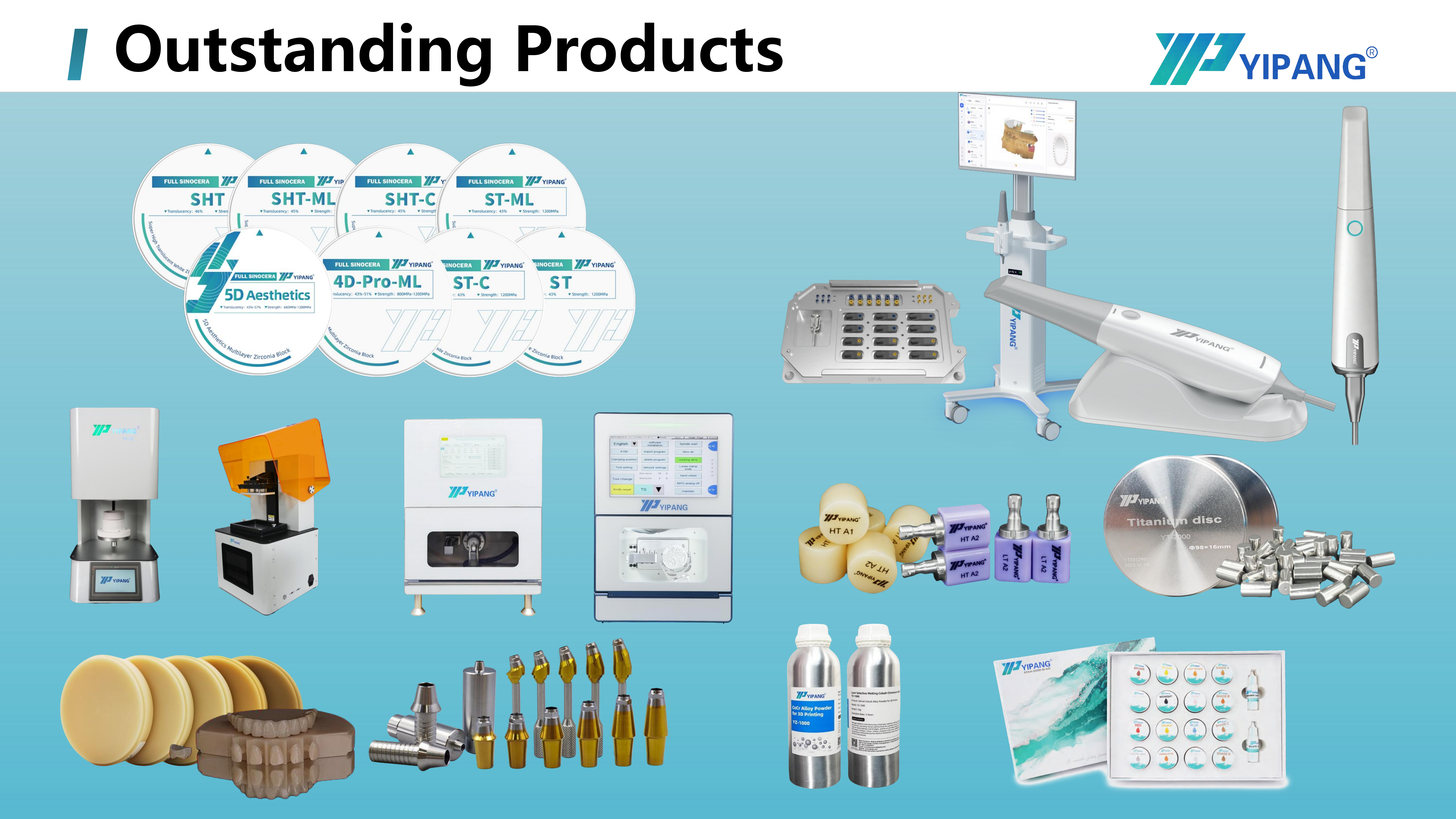
The manufacturer reports hundreds of long-term cooperative clients worldwide, including dental laboratories, clinics and distributors, working across crowns, bridges and aesthetic restorations. The stated material strengths are uniform translucency, stable sintering shrinkage and compatibility with most CAD/CAM systems, which are the three properties that keep a standardized milling and sintering protocol repeatable from case to case.
Stage 3 - Sintering: profile, tray and furnace log
Sintering converts the milled blank into a dense restoration and applies shrinkage to everything the mill produced. For the 4D-PRO-ML block, the recommended sintering temperature range is 1430 C to 1450 C, with a standard heating and holding procedure to keep shrinkage low and translucency stable.
The documented operating steps are short enough to standardize in a written work instruction:
- Place the milled zirconia workpiece on the sintering tray.
- Set the heating curve up to 1430 C to 1450 C with the appropriate holding time.
- Allow natural cooling after the sintering cycle completes.
Two safety rules belong in the same instruction: avoid rapid temperature change to prevent cracking, and never exceed the maximum sintering temperature. Furnace condition matters as much as the program. Heating elements and thermocouples drift over time, so the effective profile changes even when the set program has not. A run log covering program, load, tray layout and result is the cheapest fit-control instrument a lab owns. Long-span bridges should be supported on the tray so that they do not sag or distort during the cycle.
Stage 4 - Finishing without destroying the fit
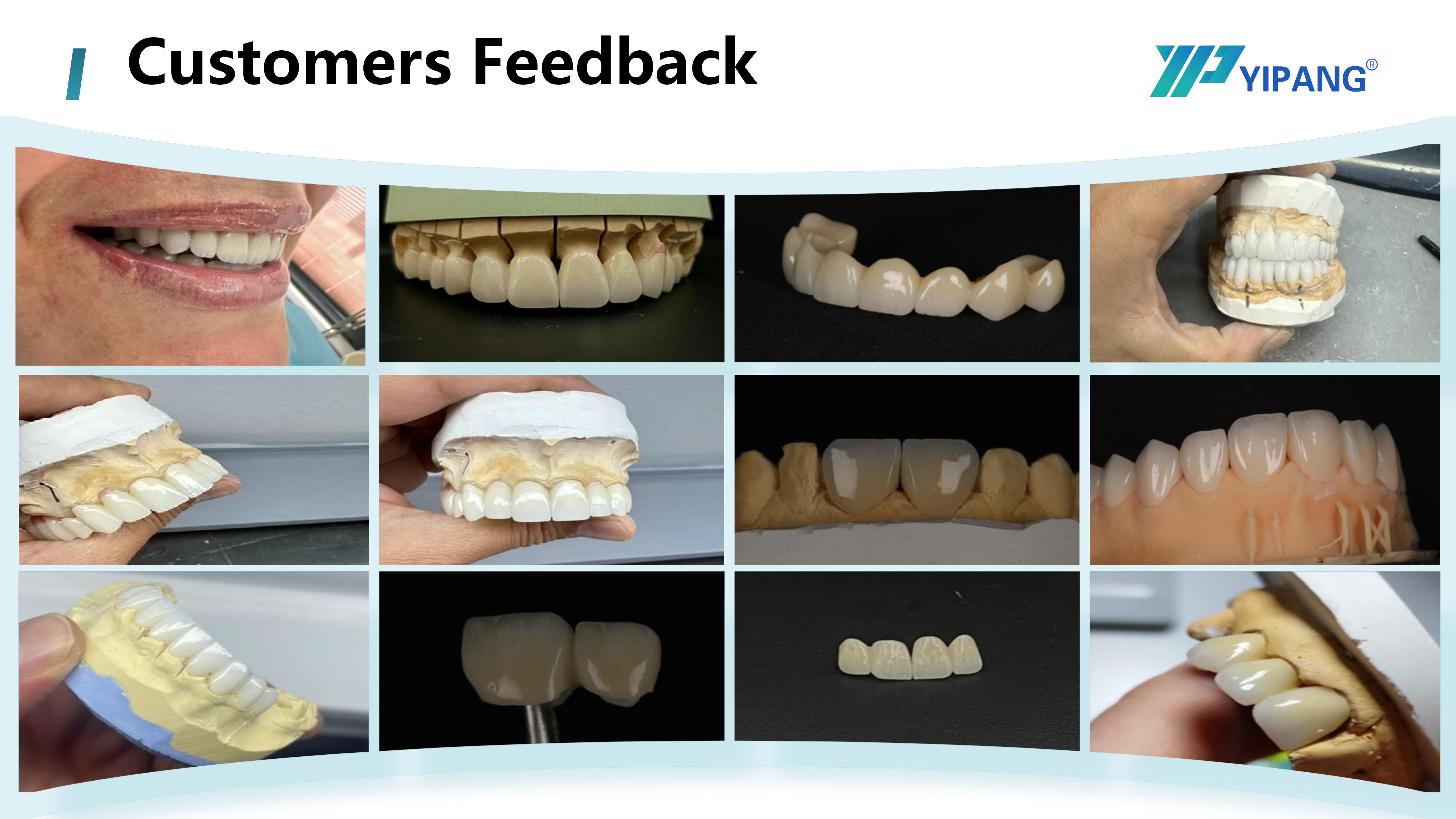
Much of the marginal damage in a lab happens after a crown has sintered correctly. Margins are finished with dental polishing burs, and pressure applied to the intaglio side of a margin can open a fit that was accurate only minutes earlier. Keep polishing on the external surface.
Characterization is the second risk. A dental staining glaze or a dental glaze paste applied too close to the margin can add thickness, and stains mixed with a dental firing paste are typically fired in a dental porcelain furnace at temperatures well above the sintering cycle. Keep characterization materials away from the fit surface, and re-check the seat on the analog after every firing cycle rather than only before it.
Step-by-Step Breakdown: A Six-Step Fit-Correction Protocol
Used in order, this sequence identifies the stage responsible for a misfit without repeating work. The principle behind it is simple: verify the cheapest variable first and the most expensive variable last.
| Step | What to verify | Symptom that points here | Correction |
|---|---|---|---|
| 1 | Scanbody seating and scan quality, using an intraoral or dental lab scanner | Every restoration from the case is off, including the model itself | Re-seat the scanbody and re-scan; do not compensate in CAD |
| 2 | Design: spacer, implant library, contact strength, screw channel | Margin closes but contacts are wrong; the screw binds | Correct the library and spacer values, then re-mill |
| 3 | Green-state dry fit on the abutment analog | Crown does not seat before sintering | Milling or design error; stop and correct upstream |
| 4 | Blank condition and bur condition | Margin under-milled, taper error, chipping before sintering | Replace dental milling burs; scrap defective blanks |
| 5 | Sintering program, tray layout and furnace log | Green crown seats, sintered crown does not | Re-run with the validated 1430 C to 1450 C profile and natural cooling |
| 6 | Post-sinter contact and margin check, then finishing | Contact drifted after sintering; margin damaged after polishing | Re-check on the analog; keep polishing and glaze off the intaglio surface |
The decision rule that comes out of this table is worth writing on the wall of the milling room. If the green crown seats and the sintered crown does not, the problem is sintering. If neither seats, the problem is data or milling. If both seat but the contact is wrong, the problem is design or shrinkage.
Verifying Contacts with Digital Scanbody Workflows
Digital verification is what makes the protocol affordable in a working lab, because it moves the check earlier. Instead of testing contacts only on the finished restoration, the lab scans the milled green crown seated on the model with a dental lab scanner and superimposes the result on the scanbody data set used in design. Contact and margin deviations then become visible before the crown enters the dental sintering furnace, while the blank can still be re-milled.
Three checks are worth standardizing:
- Scanbody reference check: confirm that the analog position in the working model matches the scanbody position recorded at acquisition, especially in full-arch cases built from an edentulous scanbody kit.
- Green-state contact check: compare interproximal and occlusal contacts in the green state against the designed values, and record the difference.
- Post-sinter comparison: scan the same crown after sintering and compare the two digital models. A deviation that appears only in the second model is a sintering behaviour rather than a design error, and it is the point at which the shrinkage stability of the block matters most.
Printed working models are a common companion to this step. A dental 3D printer and dental 3D printer resin produce the verification model quickly, while parts made from dental 3D printing metal powder cover the metal side of the same workflow when a case calls for it. Together with zirconia, lithium disilicate glass ceramic, press ingots, titanium alloy discs, PMMA discs, PEEK discs and wax discs, they form the ordinary material set a mixed-material implant lab works from every day.
Use Cases: Four Lab Scenarios and Their Fit Risks
Fit risk is not evenly distributed across implant work. It concentrates in cases where the tolerance chain is longest or the reference is weakest.
| Scenario | Dominant fit risk | First checkpoint | Typical correction |
|---|---|---|---|
| Single posterior implant crown | Marginal gap and occlusal high spot | Green-state dry fit | Verify bur condition and spacer value; correct occlusion in CAD |
| Multi-unit implant bridge | Shrinkage distortion across the span; interproximal contact drift | Sintering program and tray support | Support the span on the tray; re-check contacts digitally after sintering |
| Full-arch or edentulous restoration | Scanbody reference error accumulating across several implants | Scanbody acquisition with an edentulous scanbody kit | Re-scan and re-verify analog positions before milling anything |
| Chairside or same-day restoration | Process drift under time pressure; skipped bur checks and green-state checks | Maintenance log and written work instruction | Hold the validated sintering curve and the green-state check even when time is short |
Comparison: Material and Process Facts for Implant Superstructures
Zirconia is one option among several in an implant lab, and the protocol above is specific to materials that are milled in a green state and densified afterwards. The table uses published data points and manufacturer specifications only.
| Material or format | Published data point | Typical role in implant workflows |
|---|---|---|
| Dental zirconia block, YIPANG 4D-PRO-ML | 98 mm diameter; 10 to 20 mm thickness options; ML Multilayer shades; sintering temperature 1450 C (manufacturer specification) | Milled monolithic implant crowns and multi-unit superstructures |
| Zirconia discs as a category | Largest revenue share of the zirconia-based dental materials market at 63.1% in 2025 (Grand View Research) | Dominant CAD/CAM blank format for zirconia restorations |
| Dental lithium disilicate glass ceramic and press ingots | Approximately 28% of all all-ceramic dental restorations globally as of 2024 (Business Research Insights); market projected to grow from USD 320 million in 2025 to USD 920 million by 2032 at an 18.8% CAGR (Intel Market Research) | Esthetic single-unit and anterior work in mixed-material labs |
| Dental titanium alloy disc and dental implant abutment | Final abutment market valued at nearly USD 2.6 billion in 2025 (iData Research) | Custom abutments and metal components inside the same implant workflow |
| Dental PMMA disc, dental PEEK disc, dental wax disc | Listed product formats; no comparative performance figure is cited here | Provisionals, verification models and patterns that support fit checks before final milling |
One caution on mixing processes: pressing lithium disilicate and sintering zirconia are different thermal processes that do not share a failure mode. The corrections in this guide apply to the milled-and-sintered zirconia workflow, and a lab running both should keep the two procedure cards separate.
Frequently Asked Questions
Is YIPANG dental zirconia block production covered by a quality certification?
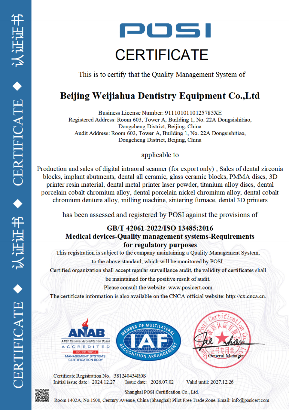
Yes. Beijing Weijiahua Dentistry Equipment Co.,Ltd, the manufacturer behind the YIPANG brand, holds ISO 13485 certificate 381240434R0S, issued by Shanghai POSI Certification Co., Ltd. on 27 December 2024 and valid until 26 December 2027, against GB/T 42061-2022 / ISO 13485:2016. The certificate scope covers the design, production and sales of dental medical materials and dental equipment, for global, EU, USA and Middle East markets. Labs supplying EU customers should also note that EU MDR 2017/745 classifies most dental implants and restorative materials as high-risk devices requiring intensive clinical data, so material documentation should be filed with the case records.
What should a CAD/CAM dental lab check in an OEM dental zirconia block manufacturer?
Three things: production flexibility, quality control and interface compatibility. YIPANG provides OEM and ODM production services with customization options for almost all specifications, backed by a monthly capacity of 15,000 pieces and a quality control process of 100% raw material inspection plus finished product random inspection. For a milling lab, compatibility is the practical test: the manufacturer reports uniform translucency and stable sintering shrinkage, with compatibility across most CAD/CAM systems. OEM and ODM projects support custom product development and private labeling, and the company R&D team includes 25 professional engineers working on dental material formula research, process optimization and new product development.
What are the minimum order quantity and payment terms for zirconia blocks?
MOQ is negotiable and small volumes are accepted: 1 box for standard models and 5 boxes for customized products. Payment terms are full payment before shipment. Domestic orders are delivered by express, while export orders ship by sea or air freight, with FOB Shanghai/Tianjin available.
Can a lab test a sample before placing a full order?
Yes. Sampling tests are supported so that a lab can run a block through its own milling and sintering protocol before committing to volume. The stated acceptance procedure is to check quantity on receipt and to report damage or deformation within 48 hours with photographs.
What is the lead time, and what after-sales support is included?
Lead time is 15 to 30 working days. After-sales support covers online technical guidance, with a response to after-sales problems within 24 hours, which is useful when a lab wants a second opinion on a sintering or milling variable. To start, send your lab own milling and sintering parameters for a technical check against the recommended profile, or request a sample, a quotation or the full catalog from the contact details below.
Conclusion: Fit Is Controlled Before Sintering, Not After
Zirconia implant crown fit problems are created in sequence and should be corrected in sequence: scanbody data first, milling second, sintering third, finishing last. A green-state dry fit on the abutment analog tells you whether the error belongs to data and milling or to the furnace. A digital scan comparison before and after sintering tells you whether the deviation is design or shrinkage. A furnace log turns an unpredictable process into a record you can read.
The dental zirconia block itself contributes one variable to that chain, shrinkage stability, plus the specifications a lab builds its CAM strategy around: 98 mm diameter, 10 to 20 mm thickness, ML Multilayer shades and a 1450 C sintering temperature for the YIPANG 4D-PRO-ML block.
Next Step: Check Your Parameters With the Manufacturer
Send your lab milling and sintering parameters, or request a sample of the YIPANG 4D-PRO-ML dental zirconia block, and the technical team will compare them against the recommended 1430 C to 1450 C profile. OEM and ODM projects are supported, with customization available for almost all specifications.
Contact: Jaye Yang | service@yipangdental.com | +86 158-0156-5064 | WhatsApp
Website:www.yipangdental.com | Company brochure (PDF):WJH Company Information
About the Manufacturer
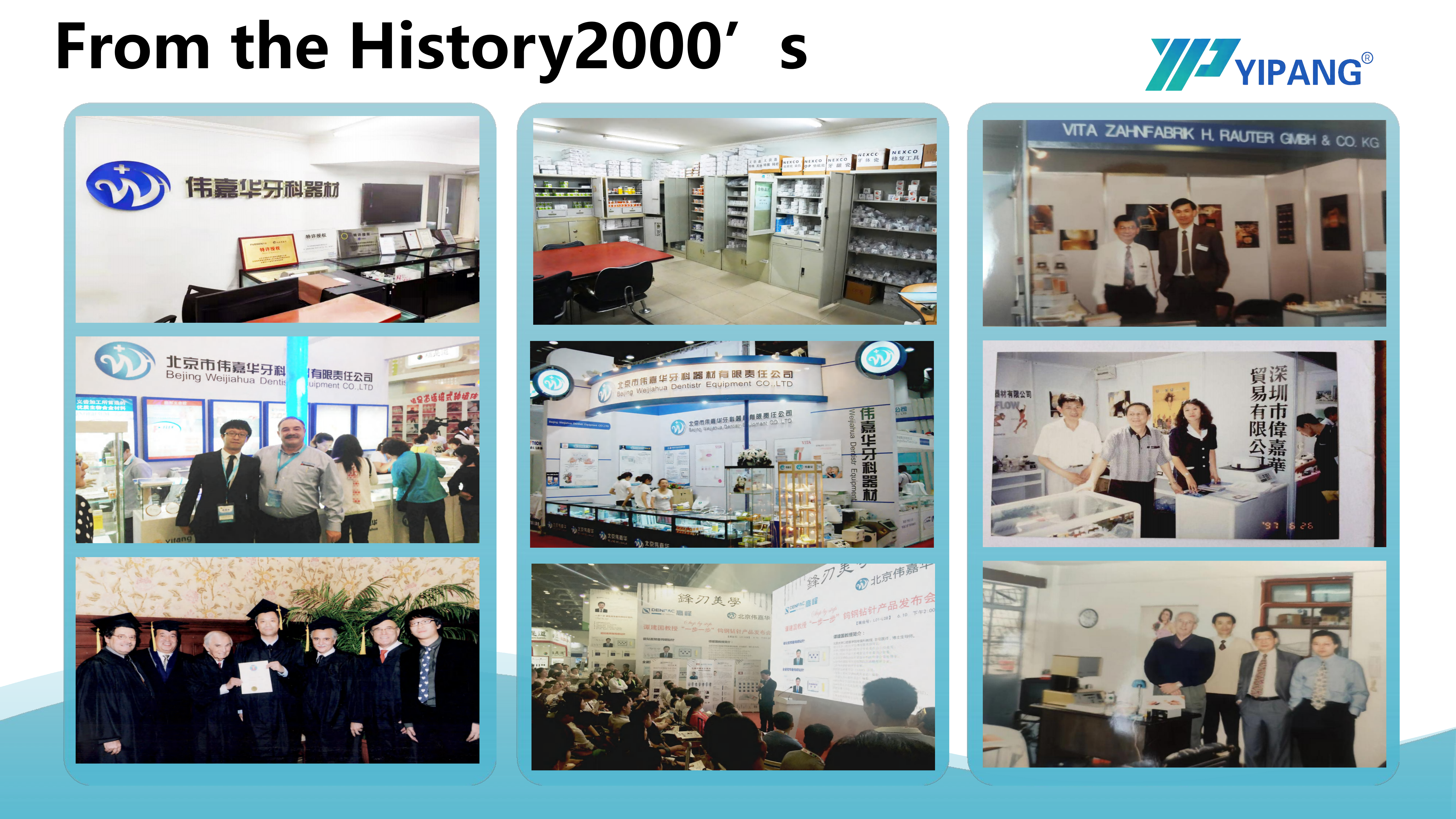
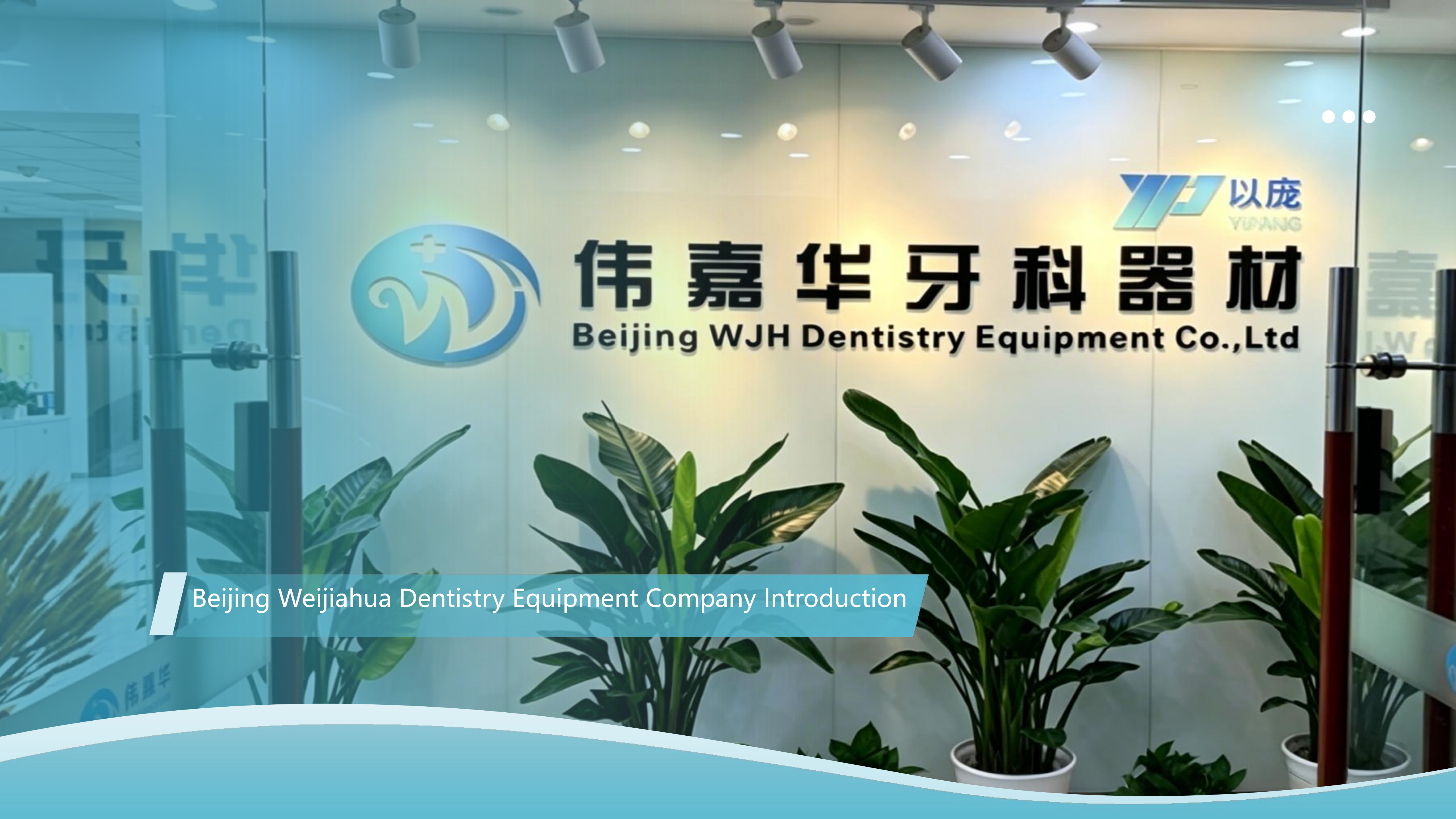
Beijing Weijiahua Dentistry Equipment Co.,Ltd was established in 1996 and is based in Beijing, China. The company manufactures and supplies dental materials and equipment under the YIPANG brand, including zirconia blocks, glass ceramics, press ingots, PMMA, wax, titanium blocks, implant abutments, intraoral scanners, milling machines, 3D printers and sintering furnaces. Its stated export markets are the Middle East, Southeast Asia, South America, North America, Eastern Europe, North Africa and Australia, with exports representing 40% to 55% of sales. Address: Room 603, Tower A, Building 1, No. 22A Dongsishitiao, Dongcheng District, Beijing, China.
Have Questions or Need More Details?
Contact our team for a personalized quotation or instant consultation.
Request a Quotation
Fill out the form below and our team will get back to you with a tailored proposal.
WhatsApp Direct Chat
Prefer to chat in real-time? Message us on WhatsApp for instant assistance & quick answers.
- Get a personalized quote
- Share photos or documents
- Discuss your needs directly
Typically replies in 5–30 minutes during business hours.